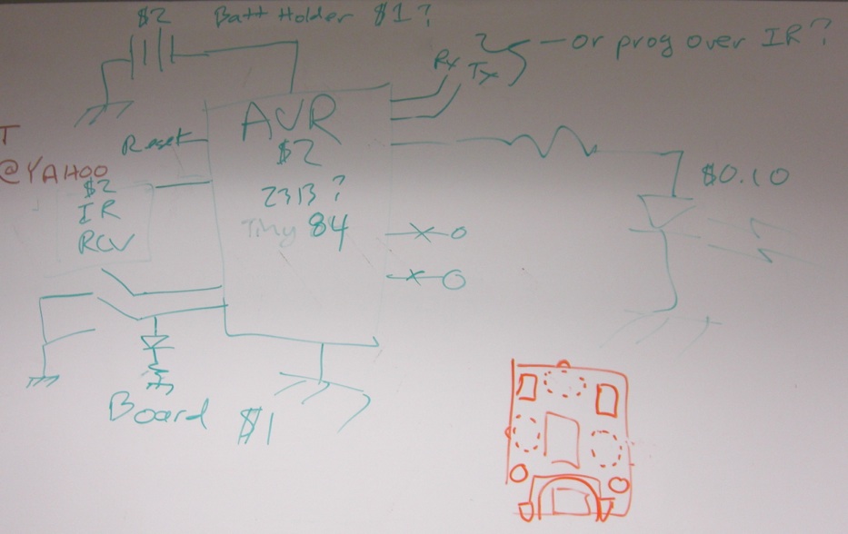
A quick and cheap design for a IR based communication board targeted for the Feb 2, 2010 DorkBot batch pcb layout that will give us something to start playing with simple communication protocols. The goal is to build up a bunch at low cost that we can strap to the back of Steve’s Zipbot collection and test the efficiency of message passing protocols.

Requirements
Small (0.5″ x 1″ max?)
Cheap (<$10; $5 stretch goal)
Bidirectional IR communication over short (<2″) distances
Self-contained (battery powered)
Reprogrammable, preferably via UART to keep programmer costs down.
Preferably AVR based due to group familiarity
Preferably Arduino compatible for ease of accessibility by newbies
Schematic
Version A1 (Ordered!):
Version C2: (Ordered!)
NOTE 1: Some component part #’s like the transistor and catch diodes are not correct — they are just placeholders.
NOTE 2: There is a mistake on D6 and D7. They need to go to V+ so they are across the motors, not to ground as they are here. Original boards all have this error.
Layout
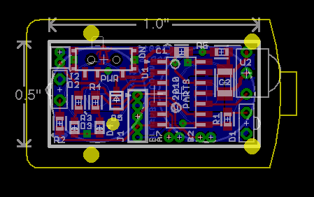
1st pass complete. This one does not not use battery holders. Instead, there is a positive and negative terminal on the bottom that two button cells can be pressed up against. A bus bar on the other side of the batteries completes the circuit. I figure we could laser-cut some acrylic for a battery holder.
Version A1 (Ordered!):
Version C2 (Ordered!):
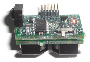
Assembled board
Click here for assembly details.
Version A1:
Version C2:
Version C2 w/ Battery Board:
Software
Testing
Results from various testing to determine component values, software parameters, etc.
Components
Price breaks chosen for a target of 20-25 units.
Board
0.5″ x 1″ — $2.50/3; double-sided; solder-mask & silk screen
0.7″ x 1″ — $3.50/3; double-sided; solder-mask & silk screen
Processor
attiny44A — $1.37 (25); soic14; 12 IO; 1.8-5.5V up to 4MHz; 2.75.5V up to 10MHz; 4.5-5.5V up to 16MHz (8MHz internal osc)
No hardware UART — implement in software
No native Arduino support (ditto for all atTiny’s), but may be able to leverage work of LumiNet project?
0.35mA @ 2.7V, 1MHz; 1.1mA @ 2.7V, 4MHz; 2mA @ 2.7V, 8MHz (“active current draw”)
attiny84v — $1.85 (25); soic14; 12 IO; 1.8-5.5V up to 4MHz; 2.75.5V up to 10MHz (8MHz internal osc)
Twice the flash as the tiny44; A bit higher power draw, (not a “A” version)
0.37mA @ 2.7V, 1MHz; 1.5mA @ 2.7V, 4MHz; 2.5mA @ 2.7V, 8MHz (“active current draw”)
attiny2313 — $1.55 (25); soic20; 18 IO; TOO BIG
Hardware UART
No native Arduino support (ditto for all atTiny’s), but may be able to leverage work of LumiNet project?
Significantly larger footprint than the attiny44Aatmega168 — $2.71 (25); tqfp32; 23 IO; TOO B
IG
Overkill for this board, bigger and more expensive than desired, but has a UART and is natively supported by Arduino
IR Receiver
TSOP36238TR — $1.43 (1); 7.5 x 5.3 x 4 mm SMT; 950nm; 38kHz; 2.7-5.5V; top view though (side view wo
uld be preferable)1.2mA @ 3.0V?
GP1UX311QS — $0.58 (10); 8.8 x 5.5 x 5.3 mm T/H; ???nm; 38kHz
; 2.7-5.5V; side view0.27mA @ 3.0V — Does not work well with two hearing-aid batteries — supply requirement too high. Actually worked best with emitters modulated at 1/2 frequency for some reason.
TSOP34338 — $1.085 (10); 6.95 x 6.0 x 5.6 mm T/H; 950nm; 38kHz; 2.5-5.5V; side view; 35mA @ 3.3V — Works well with two LR44 sized batteries.
IR Transmitter
NOTE: Dimensions below in the form of H x W x D, where H is the distance to the LED’s t
op from the top of the PCB.Power: Assume target of 1mA @ 2.7V.
LTE-302 — $0.20 (10); 5.72 x 4.4 x 2.25 mm T/H (2.54mm pitch); 940nm; 40deg; side view
t=”_blank”>GL4800E0000F — $0.30 (10); 5.6 x 3.0 x 1.5 mm T/H (2.54mm pitch); 950nm; 60deg; side viewAPECVA3010F3C — $0.216 (25); 1208 SMD (1 x 3 x 2); 940nm; 12
0deg; side view
Surface mount, so wouldn’t be able to adjust angle.
LEDs
Power: Target 1mA @ 2.7V
Pete has some surplus 0603 sized LEDs we can use
Battery
Single Li Coin cell? Many have pretty high internal resistance though.What’s our expected current draw? Looks like ~2-5mA.
LR44
> — $1.12/2 (50 pairs); 11.6 x 5.4 mm; 1.5V; 115mAh; 20 ohms;What the BrushBot uses. Would need two to get >2.7V for microcontroller and sensor.
357-303 — $0.98 (100);
11.6 x 5.4 mm; 1.55V; 175mAh; 2-8 ohms
Same size as LR44Would need two to get >2.7V for microcontroller and sensor.ZA675 — $5.62/6 (10 sets); 11.6 x 5.4 mm; 1.4V; 650mAh; ? ohms (
title=”Renata ZA675 zinc-air hearing aid battery data sheet” href=”http://www.renata.co
m/pdf/hearingaid/DBZA675maratone%20V03.pdf” target=”_blank”>data sheet shows a cont
inuous draw of ~2mA, and pulses up to 24mA)Same size as LR44
Hearing aid battery — air activated, so limited life time once activated.
Would need two to get >2.7V for microcontroller and sensor, but that doesn’t give much margin.
AC675 — $4.14/4 (10 sets); 11.6 x 5.4 mm; 1.4V; 635mAh;
Same size as LR44
Appears to have a higher internal resistance than ZA675 (lower voltage under load shown in datasheet)
Hearing aid battery — air activated, so limited life time once activated.
Would need two to get >2.7V for microcontroller and sensor, but that doesn’t give mu
ch margin.
Smaller optionsAC13-4AP — $4.14/4 (10 sets); 7.9 x 5.4 mm; 1.4V; 280mAh; NO HOLDERSZA13DP6 — $4.90/6 (10 sets); 7.9 x 5.4 mm; 1.4V; 280mAh; NO HOLDERS
Battery holder
Keystone 2997 — $0.42 (1); for 11.6 x 5.4 mm batteries; through-hole; slide-in
Fits LR44 sized batteries
Requires ~0.675″ of board width to accommodate, which would exceed the desired 0.5″ wid
th, but would still fit the bot chassis.
??? — $???; for 7.9 x 5.4 mmNone??? grrr…
Power Switch
EG2632 — $0.53 (10); slide; side; SMT; 7.2 x 6.0 x 3.5 mm (footprint)
PCM12SMTR — $0.78
(25); slide; side; SMT; 7.7 x 3.5 x 1.4 mm (footprint)
Jim Larson has had bad experience with a similar C&K switch — knob breaks off too easily
CUS-12TB – $0.77 (10); slide; side; SMT; 7.7 x 3.5 x 1.4 mm (footprint)
SSSS811101 – $0.71 (10); slide; side; SMT 7.7 x 3.5 x 1.4 mm (footprint)
AYZ0102AGRLC — $0.86 (25); slide; side; SMT; 7.2 x 4.3 x 1.5 mm (footprint)
Transistor (optional)
SOT23 package, FET. Pinout is pretty standard, so many options here.
Logic level, 1A or more.
PMV56XN,215 — $0.101 (100); SOT-23; 3.76A; logic-level; 56mOhms
Catch diodes (only if install transistors)
SOD323 package, Schottky, fast recovery. Many options here.
1A or more.
NOTE: the original Comm C board has these wired up wrong — they need to go across the motor (so from the FET’s drain to V+), not across the FET to ground.
SDM100K30L-7 — $0.41 (10); 30V; 1A continuous
PMEG3010CEJ,115 — $0.12 (25); 30V; 1A continuous; 7A repetitive peak
PMEG3005EJ,115 — $0.20 (25); 30V; 0.5A continuous; 7A repetitive peak
Connectors
0.05″ pitch. Samtec.


I mentioned the cheap basic RF wireless solution I stumbled across once… Here are links to the TX/RX boards I found. Not too bad for less than $10 per TX/RX set:
315 MHz – TX: http://www.sparkfun.com/commerce/product_info.php?products_id=8945
315 MHz – RX: http://www.sparkfun.com/commerce/product_info.php?products_id=8947
434 MHz – TX: http://www.sparkfun.com/commerce/product_info.php?products_id=8946
434 MHz – RX: http://www.sparkfun.com/commerce/product_info.php?products_id=8950
Thanks for the links Chris. See any indications on how well these guys would perform with many transmitters in the same area?
Considering how quick and dirty this is supposed to be :-), I wouldn’t worry too much about Arduino compatibility.
Good point. My main interest in Arduino compatibility was to make it easier for those new to the group w/o much microcontroller experience to get started, but, we got by pre-Arduino and we can help others get started with gcc, CodeVision, or something else. We can provide skeleton code that takes care of the hardware setup and transmitter modulation and directions on how to compile and download code.
1. Is there a pad for V+?
2. Did you decide not to add motor drive capability? I suppose it could be hacked on using an NPN transistor, with its base connected to one of the unused AVR pins through a current limiting resistor. The emitter could go to ground, and the collector to the – terminal of the brushbot’s motor…. then wire the grounds of this board and the brushbot together.
1.) No pad for V+, at least not yet… I wanted to stick one at the bottom (there’s no room at the top, after all), but V+ isn’t routed down there yet. I might be able to route down under U1.
2.) I really wanted to add a couple transistors, but I’d have to grow the board to do so. If I do so I’ll stick in protection diodes too, and preferably base resistors for noise protection.
The ZipBot chassis is big enough to allow for growing the board, which I was avoiding to keep the cost down, but it may be worth doing for the motor control and a header for battery connection. Oh, the feature creep! 🙂
The ATTiny44 comes in a QFN package as well, which could open up some room, and with the laser-cut solder paste stencils, they’re really no harder to solder..
I was briefly tempted by the QFN package, but I worried that I might scare people off. Not that this current version with SOIC’s and 0603’s won’t. 🙂 I figured I’d keep this one hand-solderable, though the hot-plate/toaster oven method is definitely the plan.
Awesome work Monty! You get a gold star!
I posted the Eagle files to github:
https://github.com/portlandrobotics/partsSwarmHardware/tree/master/BrushBot%20Eagle%20Files
BUT, there’s a mistake on the FET catch diodes, D6 and D7, that prevent the motor drivers from working on Comm board C.