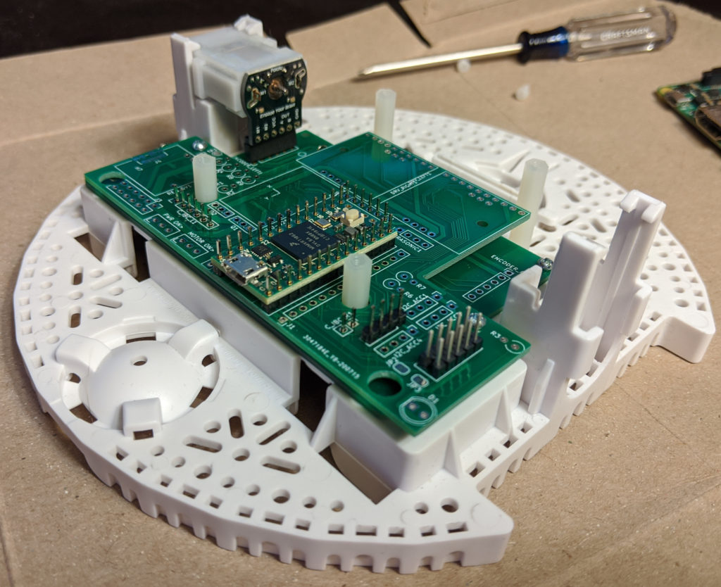
Prototypes back from PCB fab (2020-07)

Board prototyping ideas (2020-03)
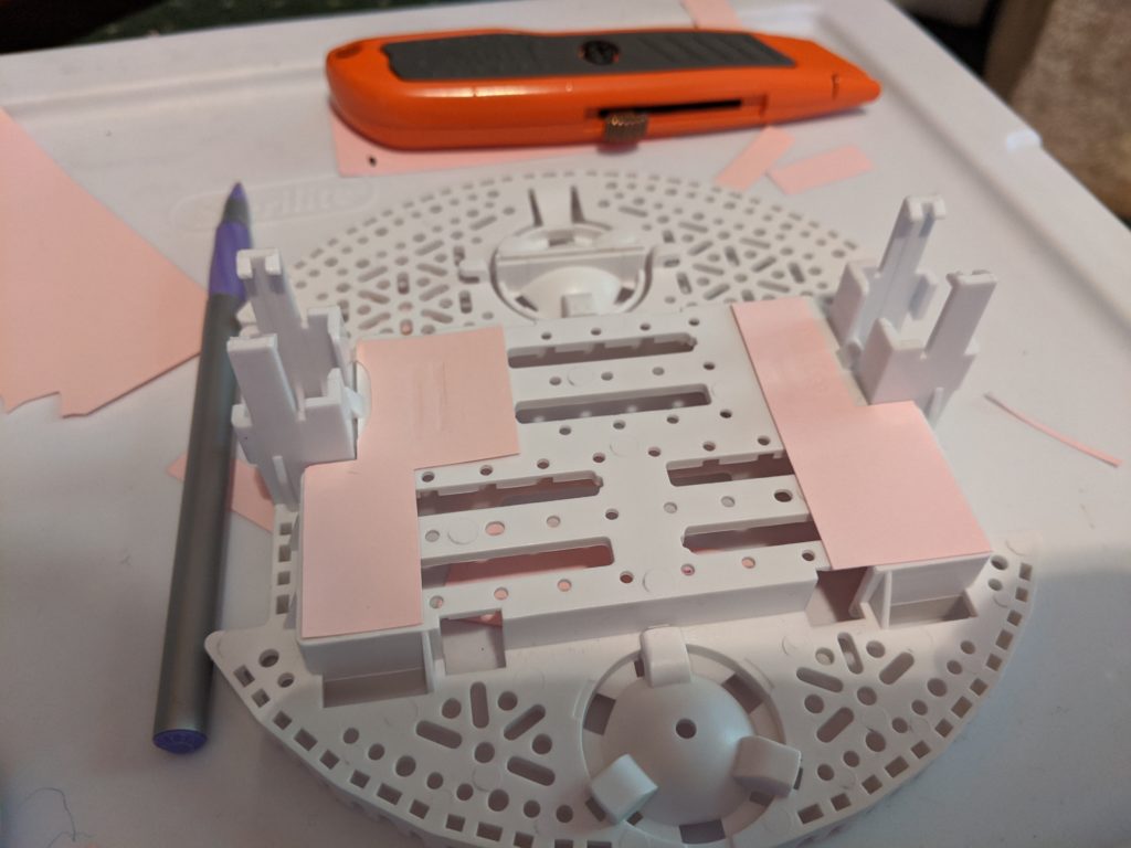
I did some experiments based on our discussion on Monday.
We came up with a 3-board plan to overcome the lack of space for the protruding pins of through-hold components, and the requirement to directly attach to the battery tabs and motor pins, which can’t accommodate stand-offs. As long as we can fit within a 10cm square, it’s a modest fee to have 3 boards instead of one.
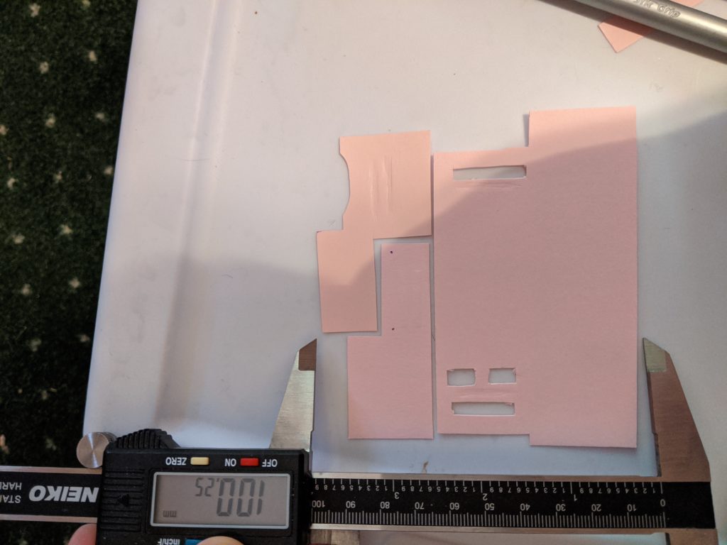
We would need cutouts for the motor headers to pass through, and I left cutouts for the upper battery tabs. The top board is a little shorter on the left “wing” to accommodate the rear batter tabs and get it down to 10cm wide.
Anywhere the boards don’t overlap, we’d have freedom to put the various through-hole connections for the teensy, Pi, motor drivers, voltage regulators, and sensors.
Using standard .1″ headers and existing cutouts in the plastic “floor,” I figure we can get 11-15 inter-board pins on the left board and 27+ to the right board, which should be sufficient.
Required left baseboard signals: Vbat, Gnd, Encoder Vdd, EncoderA, EncoderB, Motor+, Motor-
Required right baseboard signals: Gnd, Encoder Vdd, EncoderA, EncoderB, Motor+, Motor-
Optional: Left: intermediate power supply (either 2S ~2.4V or 4S ~4.8V depending on how we wire it)